
The crankcase had been lap and line bored which meant that the mating surfaces of the two halves had been refinished and polished. The curved surfaces had been realigned and polished so the crankshaft and camshaft would ride smoothly in their aluminum cradles. The case has various passageways cast into it that allows oil to pass through to various moving parts. These oil galleys are what delivers the lubrication that keeps the engine from eating itself alive.

The large openings are where the cylinders attach that are bolted to the case in eight different places. The holes that pass all the way through are for long threaded rods that pass between the case halves and hold the case together. The smaller holes toward the top of the photo are where the push rod tubes insert and contain the push rods that connect the tappets that run off the camshaft to the valves. This is known as an overhead cam engine and leads to a common design challenge that is keeping the camshaft lubricated. Gravity causes the oil to go to the bottom of the engine and the camshaft is on top, basically as far away from the oil as it can get. The camshaft gets the majority of its lubrication by oil splashing from the crankshaft and being thrown onto the camshaft.

This is one of the openings were the push rod tube fits into the case. The tappet, hydraulic plunger and socket all reside in here and you can see one of the oil galleys on the left side. The push rod tube with a wide silicone gasket sits in the recess. When oil leaks at this junction it is because the round silicone gasket at the other end of the push rod tube is not allowing the pushrod tube to float as the cylinder heats up and expands. The push rod tube pulls away from the recess and the silicone gasket becomes slightly dislodged. If a leak does develop here it's the outboard side of the tube that needs the attention and no amount of sealant around this joint will stop oil leakage.
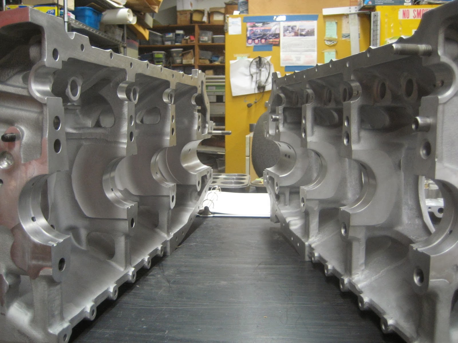
Here are the curved saddles where the crankshaft (bottom) and camshaft (top) occupy. The crankshaft has separate bearing while the camshaft uses the milled surface of the crankcase as the bearing surface. There are oil galleys for both the crankshaft and cam shaft. The oil sump bolts below the base (against the table). It is really not a very complex engine, but still amazes me what the various parts cost. We were able to re-use the old crankcase, but a new crankcase is in the range of $14,000.
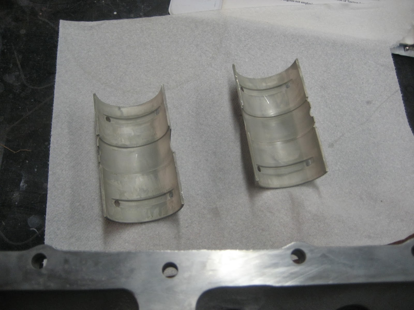
Two halves of the main bearing for the crankshaft. The holes allow for passage of oil.

The two pins help stabilize the bearing to keep it from rotating with the crankshaft.

Here Tim is putting on two different lubricants on the new camshaft. The darker is CRC engine assembly moly-garphite lubricant (http://www.crcindustries.com/ei/product_detail.aspx?id=SL3331) that went on the cam lobes and tappets. It is a high pressure lubricant that will be critical to have in place during the first start up. That camshaft surfaces that ride against the milled case surfaces that act as the bearing surface are coated with the honey colored engine assembly magic mix. Basically engine oil (Aeroshell W80 http://www.shell.com/global/products-services/solutions-for-businesses/aviation/aeroshell/products/piston-engine-oils/w65-w80-w100-w120.html) and Hyperlube (http://www.hyperlube.com/c3/Oil-Supplement-c6.html), again to provide adequate lubrication for that first critical start up.


The re-worked crankshaft after being tested and polished. This was the single most expensive piece in the engine and a new replacement crank comes in around $21,000. I was very happy to re-use this one.

The crankshaft counter weights provide a balancing force that allows the crankshaft to turn smoothly. At full RPM these weights are spinning around at about 2500 revolutions per minute. That is moving. The counterweights are held by two pins that are secured by split rings. These were one of the critical parts to verify correct assembly. The ring on the left is seated fully and the one on the right is not. Keeper rings coming loose have been responsible for the counter weights flying off the crankshafts, going through the side of the crankcase thereby causing a catastrophic engine failure in addition to being a potent projectile.

We both checked and verified three different times that those keeper rings were totally seated and locked into the retaining groove. No catastrophic failures for this engine.

Half of the crankcase with the tappets, camshaft, crankshaft, crankshaft counter weights, crankshaft main bearings, half of the other crankshaft bearings, and the crankshaft main seal.

There just isn't as much inside. Five of the six surfaces for the connecting rods are apparent along with a couple of oil galleys.

The crankshaft main bearings and the red silicone seals where either through bolts or studs go through to pull the two halves together sand connect the cylinders.


The purple Teledyne Continental Gasket Maker material was placed on the mating surfaces of the crankcase. This material had a relatively long set time to allow the case halves to be put together with less time stress than if using a faster setting material. A seal was not needed along the lower right because these holes were for the bolts that are contained within the oil sump. All of the connecting bolts were laid out in order to facilitate an accurate, and rapid assembly process once the case halves were mated.

Two strands of silk thread were embedded in the gasket making material and would form the final and secure seal.

The gears on the end of the crankshaft and cam shaft would be later connected to allow for transfer of power from the pistons via the crankshaft through the camshaft to the valves.

The tappets on the crankcase half that was on top had to held in with a clever use of rubber hose, a wooden stick and safety wire. This would allow us to lift the half on to the other and not have the tappets slide out.

The halves of the crankcase were successfully re-mated after a little finessing.


The bolts on the top and bottom were secured.
No comments:
Post a Comment